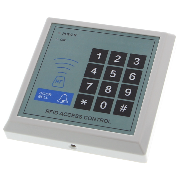
RFID access control panel Keypad lock with RFID V8.22
- Item no: F23107199
- Weight: 0,13 kg
- Packing dimensions: 11.8 cm x 11.8 cm x 2.2 cm (L x W x H)
Overview:
- This access control panel can be used without the need for microcontrollers such as Arduino.
- Use with Arduino is possible. The voltage for the door opening signal is read in.
- Operating voltage 12V DC
- Proximity reader frequency: 125 kHz
- No RFID tags are included
- Mounting material included
- The door lock mounting kit is easy to install and wire.
- Dimensions: 118 mm x 118 mm x 22 mm
Instructions:
Operating instructions - Access control reader (RFID), version: 1.2
Brief overview / quick start
1. Factory code for door opening: 111111
2. Switch to programming mode: # + 123456 (programming password). After the call, the red and blue LEDs light up continuously.
Notes
All subsequent settings must be made in programming mode.
Programming procedures (instructions for the button sequences)
Note: * = confirm/exit, + stands for the sequence of entries or actions.
1. Changing the programming code
Key input: 1 + new password + new password again (6 digits) + * → Exit
2. Change general (global) password
Key input: 2 + new password + new password again (6 digits) + * → Exit
3. Add user card (quickly by hanging up)
Key input: 3 + place the cards to be added one after the other + * → Exit
4. Add card based on card number
Enter key: 3 + enter the 10-digit card serial number (several cards can be added in succession) + * → Exit
5. Delete user card (quickly by hanging up)
Key input: 4 + place the cards to be deleted on the card one after the other + * → Exit
6. Delete card using card number
Key input: 4 + enter the 10-digit card serial number (several serial numbers in succession possible) + * → Exit
7. Create administration card (master/administrator)
Key input: 5 + insert card + * → Exit
8. Set door opening delay
Key input: 6 + time (00-60 seconds) + * → Exit
9. Data copy mode - master (for copying to another device)
Key input: 0 + 1
10. Data copy mode - slave (for receiving data)
Key input: 0 + 2
11. Set maximum volume
Key input: 0 + 3 + 0 + * → Exit
(Note: 0 here as a placeholder for "max. volume" setting; exact gradations can be set on the device)
12. Set a lower volume
Key input: 0 + 3 + 1 + * → Exit
13. Activate opening by card AND password
Key input: 0 + 7 + 1 + * → Exit
14. Open with card or general password (factory setting)
Key input: 0 + 7 + 0 + * → Exit
(Factory setting: Open by card or general password)
15. Personal password: Change allowed
Key input: 0 + 8 + 1 + * → Exit
16. Personal password: Change not permitted (factory setting)
Key input: 0 + 8 + 0 + * → Exit
17. Delete data / reset to factory settings
Key input: 0 + 9 + * → Exit
(Note: resets the controller to factory settings - user cards are deleted)
Quick functions
- Factory setting / complete reset:
In standby state, short-circuit the FUNC interface / FUNC pin for approx. 3 seconds → all settings are reset (user cards may be deleted or retained depending on the device model; in case of doubt: delete all user data).
- Quickly add cards:
Hold down long button (e.g. management card) + place cards one after the other → * to exit
- Quick deletion of cards:
Analogous to adding: Activate delete mode + hang up cards → * to exit
- Open with card + password:
Configurable - see program point 13.
- Personal user password (default):
Preset by default: 000000 (if available).
Wiring / pin assignment (brief description of the connection pins)
The following pins are usually labeled on the connection block (example assignment, read from the device):
- DO, D1 - data lines (for certain card/protocol variants)
- OPEN - door opener signal / relay output (to the door opener)
- COM - relay ground / common connection
- NO - normally closed relay (normally open)
- NC - normally open relay (normally closed)
- +12V - Supply voltage +12 V (DC)
- GND - Ground / 0 V
- BELL1, BELL2 - Connection for signal transmitter / door chime
Notes on wiring:
1. Switch off the supply voltage before connecting.
2. For electric strikes (electromagnetic lock), pay attention to polarity and required switching contacts.
3. If a door opener is operated with its own power supply unit, connect the +12 V and GND correctly; if separate power supply units are used, check the common earth (GND).
4. For push-buttons/exit buttons (PUSH1/PUSH2), connect according to the terminal assignment of the device.
Connection diagram (graphical notes)
A relay/switching diagram and a data connection diagram are shown in the manual. These typically show
- Connection of the door opener to COM / NO (or NC, depending on the desired switching behavior)
- +12 V and GND for power supply to the reader
- Connection to signaling devices and doorbells at BELL1 / BELL2
- Connections for external buttons (exit) and for a second control panel if required
Safety and operating recommendations
- Disconnect the power supply before each installation.
- Lay the cables in such a way that no moisture or mechanical stress will damage the connections.
- If the wiring is unsafe or if there are questions about compatibility with electric strikes, contact a specialist electrical company or the supplier.
- Keep documentation and passwords safe; manage master and user authorizations carefully.
BELL1 and BELL2 - Function and connection
1. Purpose
The BELL1 and BELL2 terminals are connections for an electric doorbell or an external buzzer.
They are not used to open the door itself, but to emit an acoustic signal when someone presses a bell button, for example (often via an external button with bell function in access control systems).
Typical use
External bell push connected to the PUSH1/PUSH2 inputs.
When pressed, the system activates the BELL output.
BELL1/BELL2 then control an external bell or a buzzer, which acoustically signals that someone is requesting access.
Technical notes
Only use 12 V DC bells or buzzers (no 230 V devices!).
Current consumption should be < 300 mA if the output is supplied directly from the controller.
For higher currents, always use a separate relay or power supply unit.
Keep cable length short (< 10 m recommended) to avoid voltage drop.
Scope of delivery:
- 1* RFID access control panel key lock with RFID V8.22
- 1* Operating instructions in English