
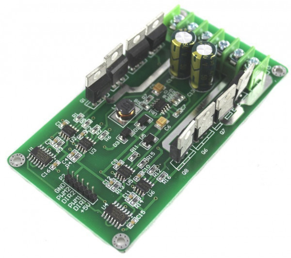

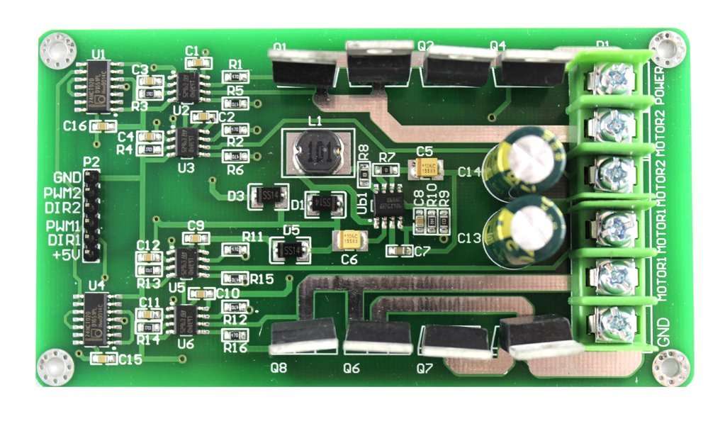


30A H-bridge with IRF3205 MOSFET transistors

€21.14 *
Content:
1 Piece
incl. VAT plus shipping costs
15 Piece in stock
Delivery time: 1-3 business days
We are known for
- Fast shipping across Germany
- 100,000+ satisfied customers
- Over 10 years of experience


- Item no: F23108636
- Weight: 0,06 kg
- Packing dimensions: 10.8 cm x 6.5 cm x 2.2 cm (L x W x H)
€21.14 *
30A H-bridge with IRF3205 MOSFET transistors
Accessories
- 50%
TIP!

")
")
 with 830 contacts")

")

 - 100cm")


, threaded rod")


- 20%
")

")


- 10%


- 50%


- 10%


