This TT DC geared motor with double shaft and integrated Hall encoder (2 channels) is ideal for precise speed measurement and direction/displacement detection in robotics and DIY projects (e.g. Arduino / Raspberry Pi, smart car, STEM). The encoder provides two phase-shifted square wave signals (H1/H2), which means that the direction of rotation can be reliably determined in addition to the speed.
Technical details
Pin assignment / connections
Encoder (Hall):
-
G = Hall supply GND
-
V = Hall supply + (typically 3.3 V or 5 V, depending on the microcontroller)
-
H1 = Hall output channel 1 (square wave)
-
H2 = Hall output channel 2 (square wave)
Motor:
-
M+ = motor supply plus
-
M- = Motor supply minus
Important:
-
The voltage V-G (encoder) depends on your controller (typically 3.3 V / 5 V).
-
The voltage M+-M- is the motor voltage (6 V or 12 V depending on the variant).
-
There is a magnetic disk on the shaft (N-/S-pole ranges).
-
The Hall sensor recognizes the poles and generates a square wave from them: e.g. high at S pole, low at N pole.
-
H1 and H2 are arranged at different positions → the signals are out of phase (quadrature).
This allows you to: -
Calculate thespeed from the frequency/period duration
-
Determinethe direction of rotation via the phase position H1 vs. H2
Speed calculation (from period duration)
If the magnetic disk P generates poles (or pole segments) and the measured period duration of the Hall square wave T is: n=60/P⋅T
-
n in rpm
-
T in seconds
-
P = number of magnetic poles/segments (depending on the magnetic disk used)
Dimensions
-
Total length: ~ 79.95 mm
-
Gearbox housing width: ~ 22.40 mm
-
Motor/housing height: ~ 25.79 mm
-
Output shaft: Ø ~ 5.40 mm
Typical applications
-
Encoder wheel / odometry (displacement measurement)
-
Robot chassis, smart car, line follower
-
Speed control (PID), RPM measurement
-
Teaching/STEM projects, prototyping
Scope of delivery
- 1x 
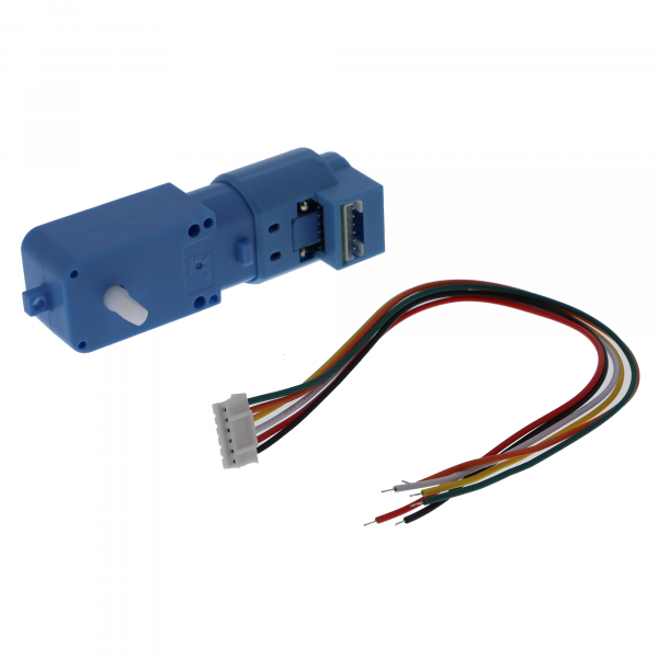
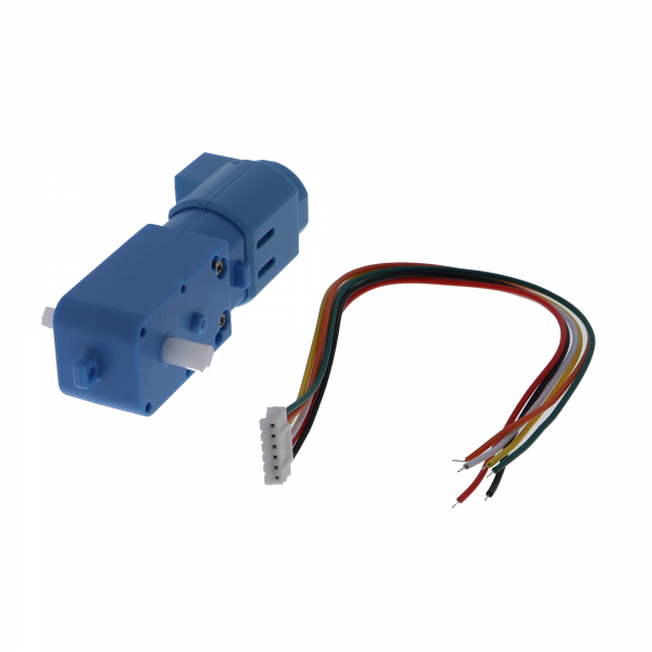
TT geared motor with Hall encoder (AB) & double shaft - 300 rpm, incl. connection cable