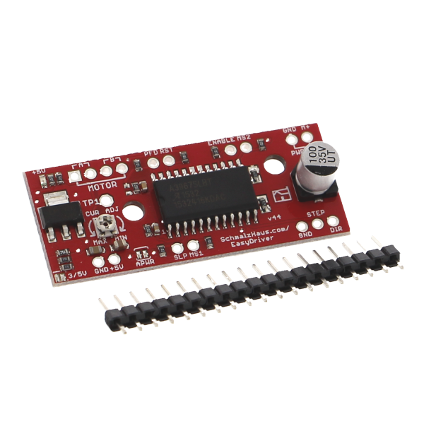
Overview:
- the "Easydriver" is an inexpensive component for driving stepper motors of various sizes
- 750mA per phase
- Adjustable step modes (full-step, half-step, quarter-step, eighth-step)
- Standard step mode eighth step (if the motor has 200 steps per revolution, the EasyDriver requires 1600 signals).
Helpful links:
M +: This is the power input of the Easy Driver. Connect this to the positive cable. This should be a clean power supply of 6 V to 30 V, 2 A (or more).
DIR (direction): This must be a digital signal from 0 V to 5 V (or 0 V to 3.3 V if you have set up your Easy Driver in this way). The level when this signal (high / low) is sampled on each rising edge of STEP to determine in which direction the step (or microstep) should be executed.
MS1 / MS2: These digital inputs control the microstep mode. Possible settings are (MS1 / MS2): Full step (0,0), half step (1,0), 1/4 step (0,1) and 1/8 step (1,1: default).
RST (Reset): This input signal resets the internal translator and disables all output drivers.
SLP (Sleep): This normally high input signal minimizes power consumption by disabling the internal circuits and output drivers when held low.
ENABLE: This normally low input signal disables all outputs when pulled high.
PFD: This one is complicated - see the datasheet for more information.
5 V: This is an OUTPUT pin that supplies either 5 V (default) or 3.3 V from the voltage regulator at a low amount of current (e.g. 50 mA - depending on the input voltage) to power a circuit that you may need to power. If you remove the APWR jumper (SJ1), you can use the 5 V pin as a VCC input for the Easy Driver and supply it with your own VCC supply.