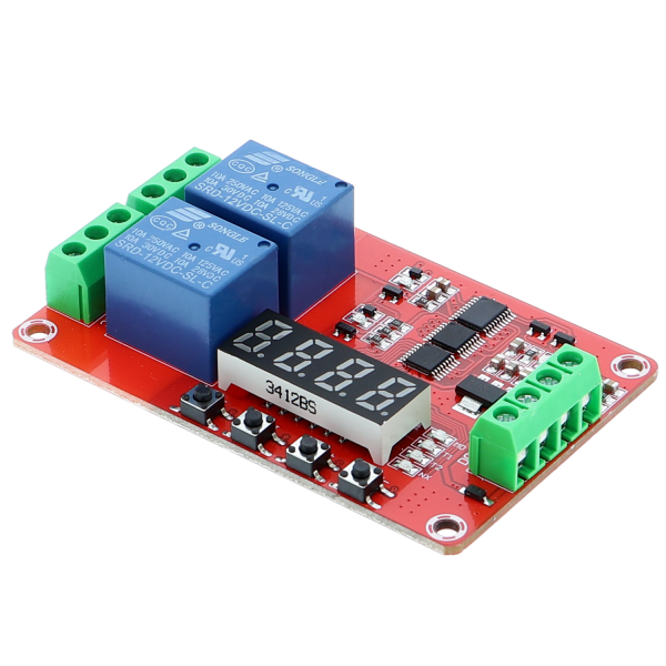
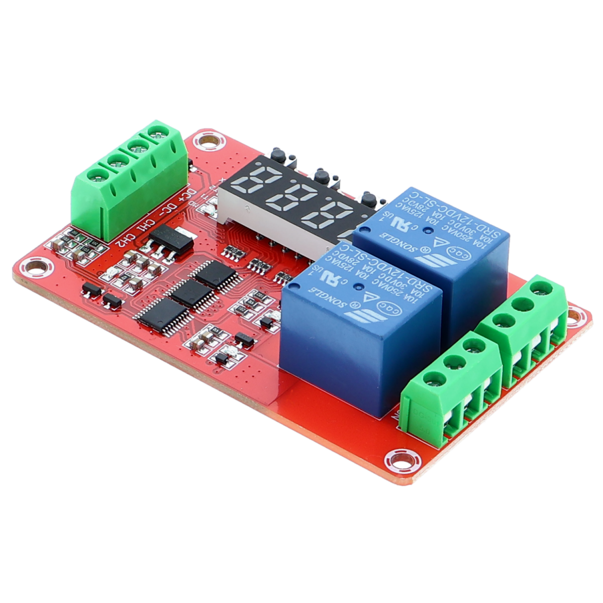
Multifunctional time relay 2-channel - Programmable - 12V
- Item no: F23108822
- Weight: 0,04 kg
- Packing dimensions: 7.7 cm x 5 cm x 2 cm (L x W x H)
Timer relay module (FRM02), 12V version (power supply for the module)
Switching voltage up to 220V AC.
Operating instructions
The multifunctional relay control module (FRM02), uses an internal microcontroller as the main control unit and includes 18 preset types of functions.
These modes can be customized based on user requirements. The two relays can be programmed separately and independently.
I. Module function
The user can select one of the following 18 types of functions using the buttons on the circuit board
Functions 1-8 start automatically after the module is switched on.
Functions 9-18 start after a signal input (high-level pulse signal trigger) with a high-level duration of ≥ 20 ms.
Mode1
Timing pull-in:
After the module is switched on, time T1 runs. As soon as T1 has elapsed, the relay is activated (switch-on delay).
T1 can be set between 0.1 seconds and 270 hours.
If a high-level signal is applied to contact CH1, the relay is deactivated and timer T1 starts again.
Mode2
Timing Disconnect: The relay is activated immediately after the module is switched on. The time T1 then runs. As soon as T1 has elapsed, the relay is deactivated (switch-off delay).
T1 can be set between 0.1 seconds and 270 hours.
If a high-level signal is applied to contact CH1, the relay is activated and timer T1 starts again.
Mode3
Timing Pull-in Then Disconnect: After the module is switched on, the relay does not pick up immediately. Timer T1 starts. As soon as time T1 is reached, the relay is activated.
Timer T2 starts. As soon as time T2 is reached, the relay is deactivated.
T1 and T2 can be set between 0.1 seconds and 270 hours.
If a high-level signal is applied to contact CH1, the mode starts again.
Mode4
Timing Disconnect Then Pull-in: After the module is switched on, the relay picks up immediately. The timer T1 starts. As soon as time T1 is reached, the relay is deactivated.
Timer T2 starts. As soon as time T2 is reached, the relay is activated again.
T1 and T2 can be set between 0.1 seconds and 270 hours.
If a high-level signal is applied to contact CH1, the mode starts again.
Mode5
Unlimited cycle time mode A: The relay does not pick up immediately after the module is switched on. The timer T1 starts. As soon as time T1 is reached, the relay is activated.
Timer T2 starts. As soon as time T2 is reached, the relay is deactivated.
The cycle then starts again.
T1 and T2 can be set between 0.1 seconds and 270 hours.
If a high-level signal is applied to contact CH1, the mode starts again from the beginning.
Mode6
Unlimited cycle time mode B: The relay picks up immediately after the module is switched on. The timer T1 starts. As soon as time T1 is reached, the relay is deactivated.
Timer T2 starts. As soon as time T2 is reached, the relay is activated.
The cycle then starts again.
T1 and T2 can be set between 0.1 seconds and 270 hours.
If a high-level signal is applied to contact CH1, the mode starts from the beginning.
Mode7
Limited cycle time mode A:
After the module is switched on, the relay does not pick up immediately.
The timer T1 starts. As soon as time T1 is reached, the relay is activated.
Timer T2 starts. As soon as time T2 is reached, the relay is deactivated.
The cycle then starts again, but only for a preset frequency. The frequency is set in the setting mode in the "NX" area.
T1 and T2 can be set between 0.1 seconds and 9999 seconds.
If a high-level signal is applied to contact CH1, the mode starts from the beginning.
Mode8
Limited cycle time mode B:
After the module is switched on, the relay picks up immediately.
The timer T1 starts. As soon as time T1 is reached, the relay is deactivated.
Timer T2 starts. As soon as time T2 is reached, the relay is activated.
The cycle then starts again, but only for a preset frequency. The frequency is set in the setting mode in the "NX" area.
T1 and T2 can be set between 0.1 seconds and 9999 seconds.
If a high-level signal is applied to contact CH1, the mode starts from the beginning.
Mode9
Self-locking mode:
When a pulse signal is applied to CH1, the relay is activated.
The relay is deactivated when another pulse is applied to CH1.
Mode10
Trigger mode:
This mode contains a delay function.
The relay is deactivated after the module is switched on.
When a pulse signal is sent to CH1, the relay is activated. Only when the signal at CH1 is deactivated does the timer T1 start. After the time T1 is reached, the relay is deactivated.
T1 can be set between 0.1 seconds and 270 hours.
Mode11
Trigger timing mode A:
After switching on, the relay is deactivated.
If a high-level signal is applied to contact CH1, time T1 runs.
As soon as T1 has elapsed, the relay is activated (switch-on delay).
T1 can be set between 0.1 seconds and 270 hours.
If a high-level signal is applied to contact CH1, the relay is deactivated and timer T1 starts again.
Mode12
Trigger timing mode B:
After switching on, the relay is deactivated.
If a high-level signal is applied to contact CH1, the relay is activated.
As soon as T1 has elapsed, the relay is deactivated (switch-off delay).
T1 can be set between 0.1 seconds and 270 hours.
If a high-level signal is applied to contact CH1, the mode starts again.
Mode13
Trigger timing mode C:
After switching on, the relay is deactivated.
If a high-level signal is applied to contact CH1, time T1 runs.
As soon as T1 has elapsed, the relay is activated (switch-on delay).
Timer T2 then starts.
As soon as T2 has elapsed, the relay is deactivated (switch-off delay).
T1 and T2 can be set between 0.1 seconds and 270 hours.
If a high-level signal is applied to contact CH1, the mode starts again.
Mode14
Trigger timing mode D:
After switching on, the relay is deactivated.
If a high-level signal is applied to contact CH1, the relay is activated.
As soon as T1 has elapsed, the relay is deactivated (switch-off delay).
As soon as T2 has elapsed, the relay is activated again.
T1 can be set between 0.1 seconds and 270 hours.
If a high-level signal is applied to contact CH1, the mode starts again.
Mode15
Unlimited cycle time mode A:
The relay is deactivated after the module is switched on.
If a high-level signal is applied to contact CH1, timer T1 starts.
As soon as time T1 is reached, the relay is activated.
Timer T2 starts.
As soon as time T2 is reached, the relay is deactivated.
The cycle then starts again.
If a high-level signal is applied to contact CH1, the mode starts again.
Mode16
Unlimited cycle time mode B:
The relay is deactivated after the module is switched on.
If a high-level signal is applied to contact CH1, the relay is activated.
As soon as the time T1 is reached, the relay is deactivated.
Timer T2 starts.
As soon as time T2 is reached, the relay is activated again.
The cycle then starts again.
T1 can be set between 0.1 seconds and 270 hours.
If a high-level signal is applied to contact CH1, the mode starts again from the beginning.
Mode17
Limited cycle time mode A:
The relay is deactivated after the module is switched on.
If a high-level signal is applied to contact CH1, timer T1 starts.
As soon as time T1 is reached, the relay is activated.
Timer T2 starts.
As soon as time T2 is reached, the relay is deactivated.
The cycle then starts again, but only for a preset frequency. The frequency is set in the setting mode in the "NX" area.
T1 and T2 can be set between 0.1 seconds and 9999 seconds.
The frequency "NX" can be set between 1 and 9999.
If a high-level signal is applied to contact CH1, the mode starts from the beginning.
Mode18
Limited cycle time mode B:
The relay is deactivated after the module is switched on.
If a high-level signal is applied to contact CH1, the relay is activated immediately.
As soon as the time T1 is reached, the relay is deactivated.
Timer T2 starts.
As soon as time T2 is reached, the relay is activated again.
The cycle then starts again, but only for a preset frequency. The frequency is set in the setting mode in the "NX" area.
T1 and T2 can be set between 0.1 seconds and 9999 seconds.
The frequency "NX" can be set between 1 and 9999.
If a high-level signal is applied to contact CH1, the mode starts from the beginning.
II Setting the operating modes
The user can set the operating mode using the buttons and the display. All parameters are saved automatically after setting.
Buttons: There are 4 buttons, namely: [SET] [SM1], [NUM +] and [NUM-],
The buttons recognize short and long presses.
Short press means that you press the button for less than 1 second.
Long press means that you press the button for more than 1 second.
Operating mode: There are 3 types, namely: [Operating mode], [Parameter view
Mode] and [Parameterization mode].
[Digital displays]: There are 4 digital displays used to set or display user timing
[LED]: 4 blue parameter indicators, 1 red operation indicator on the power connector.
[User parameters]:
4 types of parameters can be set (4 blue LED lights).
[MD]: MD, display shows the current program mode. A total of 18 modes are available for selection (01-18).
[T1]: T1 LED, display shows the time T1, can be 0-9999 seconds.
[T2]: T2 LED, display shows time T2, can be 0-9999 seconds.
[NX]: NX LED, display shows the different meanings depending on the function.
1. NX meaning
In functions 1-6 and 11-16, the NX LED in the display shows the time base.
Time base means that the numerical values entered in T1 and T2 are multiplied by the values in the NX specification.
For example: NX displays "01 01".
This means that the timing time unit is 1 second.
For example: NX displays "10 02".
This means that the timing time unit of T1 is 10 seconds, T2 is 2 seconds.
The value 10 is then multiplied by the value of T1 to calculate the timer T1.
The value 2 is then multiplied by the value of T2 to calculate the timer T2.
The maximum time can be set by this multiplication with 9999 (T1) x 99 (NX) seconds, which corresponds to approximately 270 hours.
2. NX meaning
In functions 7, 8, 17 and 18, the NX value on the display indicates how many cycles are to be carried out in the respective mode.
In these modes, the times for T1 and T2 cannot be multiplied by the "NX" value.
Operating mode
1. When the module is switched on, a short countdown starts. The current function number is then displayed.
Example: (1 - 0 1 ) means "Relay no.1 with function01.
Example: (2 - 0 1 ) means "Relay no. 2 with function01.
2. Press [SET] briefly to enter energy saving mode, the display goes out but the program continues to operate normally. Press [SET] again to restore the display.
3. Press and hold [SET] to enter parameter setting mode.
4. Long press [SWI] to enter the parameter view mode.
5. Long press [NUM+] to enter automatic power saving mode for 10 seconds.
The display flashes twice, indicating that the setting was successful. After activating the energy saving mode, if no button is pressed within 10 seconds, the display is switched off but the program continues to run.
You can also long press [NUM+] again to exit automatic mode.
6. Long press [NUM-] to reset and stop the timing. Briefly press [NUM-] again to restore the timing. After resetting, the LED lights no longer flash.
Parameter view mode
Press and hold [SWI] to enter parameter view mode. This mode can display the parameters of the current function
Briefly press the [SET] button to change the parameters.
Long press the [SM1] button to enter [Operating mode];
Parameter setting mode
Press and hold [SET] to enter parameter setting mode. Various parameters can be set in this mode, for example you can set the mode 1 to 18 and the times T1 and T2 as well as NX.
1. Briefly press the [SET] button to change the parameters, you can select one from [MD] (mode 1-18). [T1], [T2] or [NX], the LED indicator of the selected parameter shows the set parameters on the display.
2. Briefly press the [SWI] button to access the setting for time T1; the blue LED labeled T1 lights up as a check.
Use the SM1, NUM+ and NUM- buttons to set the desired time.
3. Briefly press the [SWI] button to access the setting for time T2; the blue LED labeled T2 lights up to indicate this.
Use the SM1, NUM+ and NUM- buttons to set the desired time.
4. Briefly press the [SWI] button to access the NX time setting; the blue LED labeled NX lights up to indicate this.
Use the SM1, NUM+ and NUM- buttons to set the desired numbers.
5. Press and hold the [SET] button, save the parameters and call up the operating mode.
Example 1
Control a lamp that is to be on automatically for one hour via relay no. 1 and then switch it off.
This application can use Mode2 or Mode12:
MOD="1 - 12"
T1=3600
T1="xxxx" (not required)
NX="0 1 x x "(x can be any value, not required)
Run:
1. Long press [SET] to enter the parameter setting mode;
2. The MOD LED lights up, press [NUM+] or [NUM-] and set the following on the display "1 - 12". (This corresponds to mode 12)
3. Briefly press "SET", T1 LED lights up. Now set via the display = "3 6 0 0". T2 is not required.
4. Briefly press "SET" and set at NX="0 1 0 1"
5. Press and hold [SET], save the settings and exit parameter setting mode. The function starts immediately.
Example2
When switched on, the machine runs via relay2 for one hour, then stops for 10 minutes and repeats this for 5 cycles. The machine then switches itself off.
This application can be realized with Mode8.
Parameter:
MOD="2 - 0 8"
T1="3 6 0 0"
T2="0 6 0 0"
NX="0 0 0 5"
III Wiring
Recommendation:
1. Separate cabling for the power supply of the timing relay module and the voltage to be switched.
2. Select a generously dimensioned voltage source to reduce current fluctuations.
3. Capacitor: If the two measures mentioned above do not achieve the desired effect, you can connect an electrolytic capacitor with a capacity of 470 uf/35 V or more between DC- and DC +.
III Electrical parameters
1. Operating voltage: 5 V/12 V/24 V (+/-10 %), depending on the selected module
2. Operating current:
5 V / less than 90 mA (if the relay does not operate below 15 mA, switch off the display below 3 mA)
12 V / less than 50 mA (if the relay does not operate below 15 mA, switch off the display below 3 mA)
24 V / less than 35 mA (if the relay does not operate below 15 mA, switch off the display below 3 mA)
3. Operating temperature: -20 ℃ - 60 ℃ (limit range - 30 ℃ - 70 ℃)
4. Load on the relay:
Maximum load capacity (open relay): DC 0-30 V/10 A, AC 0-250 V/10 A
Maximum load capacity (closed relay): DC 0-28 V/10 A, AC 0-125V/10A
Limitations
The relay service life is approx. 100,000 operations
IV. Module interface
Terminals at the signal input:
1.DC+:Direct current positive
2.DC-:Direct current negative
3.CH1: Input signal interface. (3V-30V)
Terminals on the relay:
1.NO: Normally open interface (NO and COM are switched through when the relay is deactivated.)
2.COM: Common interface;
3.NC:Normally closed interface (NC and COM are switched through when the relay is activated.)
V. Module size
1. Dimensions: 66 mm x 40 mm x 20 mm (L * W * H);
2. Screw size for mounting the board: 4 x 3.0 mm.
3. Center distance of the screw holes: 59 mm x 33 mm
Alles gut
Gutes Produkt, funktioniert
Leider stimmt die angegebene Größe nicht
Das Modul ist Klasse und macht was soll. Leider stimmt aber die angegebene Grüße nicht. Die Platine ist größer und deshalb hat sie nicht in mein Gehäuse gepasst.
Die Masse sind ca. 78x55 mm


