

Understanding the mobility of the future with robot cars, part 2
Welcome to the second installment of our new blog series on robotic cars. In the first part, we learned about the basics for the basic vehicle. This time, we will discuss remote control options, develop a code system to determine the speed levels of the robot car, and finally implement a simple remote control with an infrared remote control.
Why do I need speed steps for an RC car for Arduino microcontrollers?
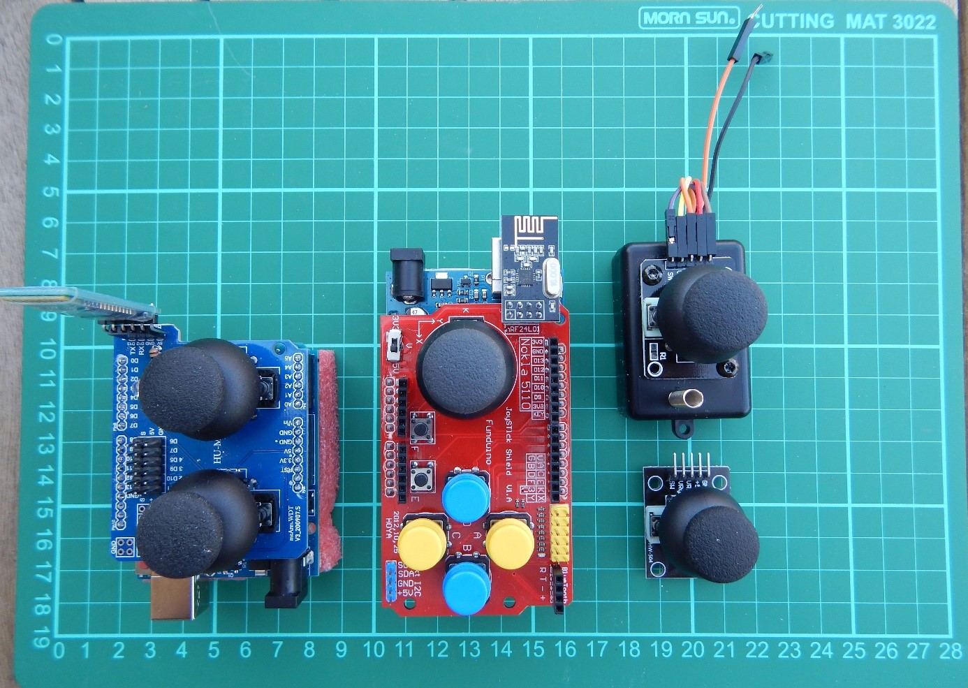
1. To control the motor speeds from another device, there is basically the possibility to use a potentiometer (poti) to continuously determine and transmit values, or to increase or decrease the value of the speed step by pressing a button. On the following pictures some selected examples, on the first picture joystick controls:
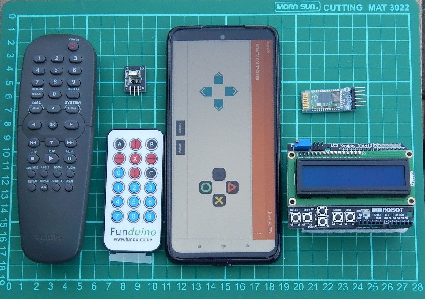
In the second picture we see infrared remote controls, a smartphone app with Bluetooth receiver, and the LCD1602 keypad shield that can be operated with a 433 MHz transceiver, among others:
To achieve a uniform scheme, it makes sense to use the map() function to reduce the analog values of the pot to values that can be transmitted via radio. The analog to digital converter provides 10 bit numbers, i.e. values between 0 and 1023. The center position of the mini joysticks is about 511. If you divide the value by 100, you can get two values (x and y direction) with one joystick, which are between 0 and 10 or if you use the map() function between 1 and 9. This is sufficient for entering the speed and for driving curves. No matter if we determine 11 or 9 values, standstill means value 5 in y-direction and for driving straight also value 5.
Looking at the controller with the two joysticks (part of the 4DOF Mini robot arm kit with joysticks and servo drive), I decide to use a code between 1111 and 9999, which is easy to transfer, considering the variety of different systems. The first digit can be used for the y-direction of the left joystick, the second digit for the x-direction of the left joystick, the third and fourth digit for an optional second joystick or certain keys. In the first example with the IR remote control, we only need the first two digits of the four-digit code.
The speed control of the RC Car for Arduino
The speed control of the motors is done with pulse width modulation (PWM). The value for the so-called duty cycle is an 8-bit number, i.e. a value between 0 and 255 (=2 to the power of 8 -1). If you apply voltages between 0 and 6V to the motor with an adjustable power supply, you will notice that up to approx. 1.5 V nothing is noticeable. Then the motor starts to hum, but does not move. If you measure the current at the same time, you will notice a relatively high value. The energy is converted into heat and humming - not really good. From 2.4 - 3 volts the motor starts to rotate, the amperage drops a bit when the motor is unloaded. After that, the speed increases depending on the applied voltage. When regulating the voltage down, the motor will turn down to below 2 volts, but if it comes to a stop, for example due to increased frictional resistance or an obstacle, it will not restart. Conclusion: values below approx. 2.4 volts should be avoided, the input should be set equal to 0 (zero) to prevent unnecessary wear and power consumption. Except standstill (code=5) we need Duty Cycle between approx. 40% and 100% with a supply voltage of 6V for the motors.
The power supply for the RC Car for Arduino
We have already discussed several possibilities of power supply in the first part. Four AA batteries of 1.5V each result in 6V, the maximum voltage of the small yellow motors. Four AA batteries of 1.2V each are not sufficient as power supply. You then need a battery holder for 6 batteries and that gives 7.2 volts. And two lithium-ion batteries (nominal voltage 3.7V) deliver more than 8 volts when fully charged. So it makes sense to set a factor in the program that limits the voltage of the highest drive level at 6V.
The control of the RC Car for Arduino
If the driving instructions are given with buttons, which may even be in a smartphone app, the appropriate value is increased or decreased to the output value 55xx (standstill) without exceeding the maximum.
Reading out the code correctly
The assignment of the first digit of the code to the required values of the speed steps is done via the index of a list with the respective numerical values.
Conclusion: With a four-digit code we can control speed and cornering with the first two digits, the rear two digits are used for other functions (not needed at first). So, for example, code95xx for fastest straight ahead travel, 55xx for standstill, 77xx for forward travel to the right.
|
y ↓ 0 x→ |
1 |
2 |
3 |
4 |
5 |
6 |
7 |
8 |
9 |
|
9 |
← |
|
|
↑ |
|
|
→ |
||
|
8 |
← |
|
|
↑ |
|
|
→ |
||
|
7 |
← |
|
|
↑ |
|
|
→ |
||
|
6 |
← |
|
|
↑ |
|
|
→ |
||
|
5 |
← |
|
|
0 |
|
|
→ |
||
|
4 |
← |
|
↙ |
|
↓ |
|
↘ |
|
→ |
|
3 |
← |
|
↙ |
|
↓ |
|
↘ |
|
→ |
|
2 |
← |
|
↙ |
|
↓ |
|
↘ |
|
→ |
|
1 |
← |
|
↙ |
|
↓ |
|
↘ |
|
→ |
Now we want to build our first Smart Robot Car with the kit, an ATmega328 microcontroller (design of the UNO R3), a MotorShield V2 and IR transmitter and receiver.
The Motor Shield V2 can control up to four motors. For the connection of the control lines the so-called I2C bus with the connections SDA (=Serial Data) at the analog input A4 and SCL (=Serial Clock) at A5 are used. Adafruit has also developed and provided a suitable program library for this. Attention: The libraries for Motor Shields V1 and V2 are not compatible.
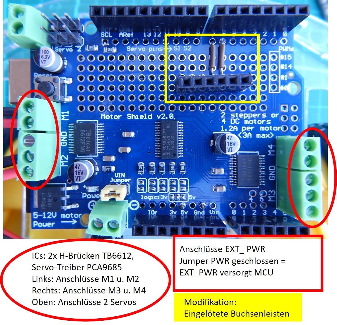
Picture Motor Shield V2 with modification:
Soldered socket connectors (female connectors) for connection of additional equipment
No matter which Motor Shield you want to use - V1 or V2 -, it makes sense to solder in additional female connectors for both Motor Shields to connect Bluetooth or 433 MHz transmitters/receivers or sensors later. More about this in the following blog posts. The IR receiver only needs power supply from pin 3 and 4 and pin2 for the IR receiver. The soldering iron can still stay cold.
For control we will first use the small infrared remote control from Funduino and an IR receiver. Although the "naked" IR sensor will do, I recommend the small breakout board, as it has an LED that flickers when IR signals are received; a valuable tool when looking for a fault.
The sketch is composed of two tried and tested parts: Armin Joachimsmeyer's example sketch, which he added to his great IRremote program library, and a Robot Car sketch by the author based on Adafruit's program library.
The program code for the RC Car for Arduino
/* Sample Code for Robot Car with Motor Shield V2 and IR receiver, as of 20220515
* based on Adafruit Motor shield V2 library, copyright Adafruit Industries LLC, 2009
* and SimpleReceiver.cpp, part of Arduino-IRremote https://github.com/Arduino-IRremote/Arduino-IRremote
* MIT License Copyright (c) 2020-2022 Armin Joachimsmeyer
* modified for Funduino
* Motor Shield V2 utilizes I2C with SDA=A4 and SCL=A5
* IRreceiver utilizes Pin 2
************************************************************************************
* Permission is hereby granted, free of charge, to any person obtaining a copy
* of this software and associated documentation files (the "Software"), to deal
* in the Software without restriction, including without limitation the rights
* to use, copy, modify, merge, publish, distribute, sublicense, and/or sell
* copies of the Software, and to permit persons to whom the Software is furnished
* to do so, subject to the following conditions:
*
* The above copyright notice and this permission notice shall be included in all
* copies or substantial portions of the Software.
*
* THE SOFTWARE IS PROVIDED "AS IS", WITHOUT WARRANTY OF ANY KIND, EXPRESS OR IMPLIED,
* INCLUDING BUT NOT LIMITED TO THE WARRANTIES OF MERCHANTABILITY, FITNESS FOR A PARTICULAR PURPOSE AND
* PARTICULAR PURPOSE AND NONINFRINGEMENT. IN NO EVENT SHALL THE AUTHORS OR COPYRIGHT
* HOLDERS BE LIABLE FOR ANY CLAIM, DAMAGES OR OTHER LIABILITY, WHETHER IN AN ACTION OF
* CONTRACT, TORT OR OTHERWISE, ARISING FROM, OUT OF OR IN CONNECTION WITH THE SOFTWARE
* OR THE USE OR OTHER DEALINGS IN THE SOFTWARE.
*************************************************************************************/
#include <Adafruit_MotorShield.h>
// Create the motor shield object with the default I2C address 0x60
Adafruit_MotorShield AFMS = Adafruit_MotorShield();
// Select which 'port' M1, M2, M3 or M4.
Adafruit_DCMotor *motor1 = AFMS.getMotor(2);
Adafruit_DCMotor *motor2 = AFMS.getMotor(3);
// define protocol for remote control, for more see samples code SimpleReceiver.cpp
#define DECODE_NEC // Includes Apple and Onkyo, also for tiny Funduino remote control
//#define INFO // To see valuable informations from universal decoder for pulse width or pulse distance protocols
#define IR_RECEIVE_PIN 2 // instead of #include "PinDefinitionsAndMore.h"
#include <Arduino.h>
#include <IRremote.hpp>
// IR Receiver signal connected to Pin2, VCC to Pin3, GND to Pin4
int IR_GND = 4;
int IR_VCC = 3;
int x = 0;
int y = 0;
int left = 0;
int right = 0;
int code = 5555;
int speedL = 0;
float factor = 1.8; // Correction for speedLevel 255/100 * 6V/VBatt
void setup() {
Serial.begin(9600);
Serial.println("Motor test!");
Serial.println("Motorshield v2 - DC Motor test!");
if (!AFMS.begin()) { // create with the default frequency 1.6KHz
Serial.println("Could not find Motor Shield. Check wiring.");
while(1);
}
Serial.println("Motor Shield found.");
// Just to know which program is running on my Arduino
Serial.println(F("START " __FILE__ " from " __DATE__ "\r\nUsing library version " VERSION_IRREMOTE));
// Start the receiver
IrReceiver.begin(IR_RECEIVE_PIN); //, ENABLE_LED_FEEDBACK);
Serial.print(F("Ready to receive IR signals of protocols: "));
printActiveIRProtocols(&Serial);
Serial.print(F("at pin "));
Serial.println(IR_RECEIVE_PIN);
// initialize digital pins as output for power supply
pinMode(IR_GND,OUTPUT);
pinMode(IR_VCC,OUTPUT);
digitalWrite(IR_GND,LOW);
digitalWrite(IR_VCC,HIGH);
} // end setup
void loop() {
if (IrReceiver.decode()) {
// Print a short summary of received data
IrReceiver.printIRResultShort(&Serial);
if (IrReceiver.decodedIRData.protocol == UNKNOWN) {
// We have an unknown protocol here, print more info
IrReceiver.printIRResultRawFormatted(&Serial, true);
}
Serial.println();
/*
* !!!Important!!! Enable receiving of the next value,
* since receiving has stopped after the end of the current received data packet.
*/
delay(100); // Debounce, no fast retry
IrReceiver.resume(); // Enable receiving of the next value
/*
* Finally, check the received data and perform actions according to the received command
*/
if (IrReceiver.decodedIRData.command == 0x46) {
if (code<9000) code = code + 1000;
Serial.print("code = ");
Serial.println(code);
}
else if (IrReceiver.decodedIRData.command == 0x15) {
if (code>2000) code = code - 1000;
Serial.print("code = ");
Serial.println(code);
}
else if (IrReceiver.decodedIRData.command == 0x43) {
if ((code-1000*int(code/1000))<900) code = code + 100;
Serial.print("code = ");
Serial.println(code);
}
else if (IrReceiver.decodedIRData.command == 0x44) {
if (code-1000*int(code/1000) > 200) code = code - 100;
Serial.print("code = ");
Serial.println(code);
}
else if (IrReceiver.decodedIRData.command == 0x40) {
code = 5555;
Serial.print("Code = ");
Serial.println(code);
}
else {
Serial.print("invalid code");
}
motor();
}
} // end loop
void motor(){
int speedLevel[9]={-100,-80,-60,-40,0,40,60,80,100};
y = int(code / 1000);
x = int((code - 1000*y) / 100);
speedL = speedLevel[y-1];
Serial.print("code = ");
Serial.print(code);
Serial.print(" y = ");
Serial.print(y);
Serial.print(" x =");
Serial.print(x);
Serial.print(" speedL =");
Serial.println(speedL);
//Correction of speed steps for curve travel
if (x==1){
right = speedL+16;
left =  speedL-16;
}
else if (x==2){
right = speedL+13;
left =  speedL-13;
}
else if (x==3) {
right = speedL+10;
left =  speedL-10;
}
else if (x==4) {
right = speedL+7;
left =  speedL-7;
}
else if (x==6) {
right = speedL -7;
left = speedL+7;
}
else if (x==7) {
right =  speedL-10;
left = speedL+10;
}
else if (x==8) {
right =  speedL-13;
left = speedL+13;
}
else if (x==9) {
right =  speedL-16;
left = speedL+16;
}
else {
right = speedL;
left = speedL;
}
//Input the speed levels for "left" and "right
Serial.print("left = ");
Serial.print(left);
Serial.print(" right = ");
Serial.println(right);
if (left < 40 & left > -40) {
motor1->run(RELEASE);
}
if (right < 40 & right > -40) {
motor2->run(RELEASE);
}
if (left>=40) {
if (left>100) left=100;
motor1->run(FORWARD);
motor1->setSpeed(left * factor);
}
if (right>=40) {
if (right>100) right=100;
motor2->run(FORWARD);
motor2->setSpeed(right * factor);
}
if (left<= -40) {
if (left<-100)  left=-100;
motor1->run(BACKWARD);
motor1->setSpeed(-left * factor);
}
if (right<= -40) {
if (right<-100)  right=-100;
motor2->run(BACKWARD);
motor2->setSpeed(-right * factor);
}
} // end motor
Explanation of the program code for the RC Car
After including the libraries for the Motor Shield V2 and IRremote, two motors are instantiated with the number at the terminal block of the controller and some global variables are declared (data type) and initialized (initial value).
In the function setup() the serial interface and the IR receiver are initialized and the pins for the power supply of the IR receiver are set up as outputs with the state HIGH or LOW.
In the function loop() first the signal of the IR remote control is received, then depending on the pressed key the code for the motor control is changed. The cursor keys up and down change the first digit, left and right the second digit of the code in the value range 1 to 9. The key X leads to standstill with code 5555. The third and fourth digit of the code are currently not yet significant. At the end, the self-defined function motor() is called without arguments, because we had defined the variables globally, i.e. valid in all functions.
In the self-defined function motor(), which we will also use in other configurations with other remote controls, the speed steps for the left and right motor are determined from the code. The percentage value of the speed level is finally converted into the PWM value for setSpeed with the factor defined at the beginning.

Now the Robot Car is ready for use. Works fine as long as you can maintain the optical connection between remote control and IR receiver. However, when driving on the road, I have experienced that strong sunlight hinders reception. That's why I'm switching to radio remote control. See you soon.

")


