

Understanding the mobility of the future with robot cars, part 3
Welcome to the third installment of our blog series on robotic cars. In the first part we learned about the basics of the basic vehicle. In the second part we developed a universal code system to define driving levels of the robot car and realized a simple remote control with an infrared remote control. Due to the physical limitations of this remote control, in this episode I would like to show the transmission of driving instructions using Bluetooth, e.g. from a smartphone to the BT receiver HC-05. Bluetooth is a 2.4GHz radio signal with short range. Safe up to about 10m and interference free in sunlight.
The Bluetooth module HC-05 is actually a transceiver=transmitter+receiver. However, we use it only as a receiver, for sending the driving instructions we use a Bluetooth APP on the Android smartphone (because of the special way of Apple with Bluetooth it does not work with an iPhone). In principle, it is also possible to build a Bluetooth remote control with the HC-05; however, this requires a second HC-05, more micro controller and an input device (joystick controller).
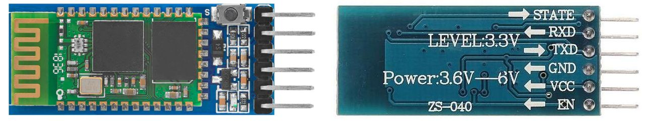
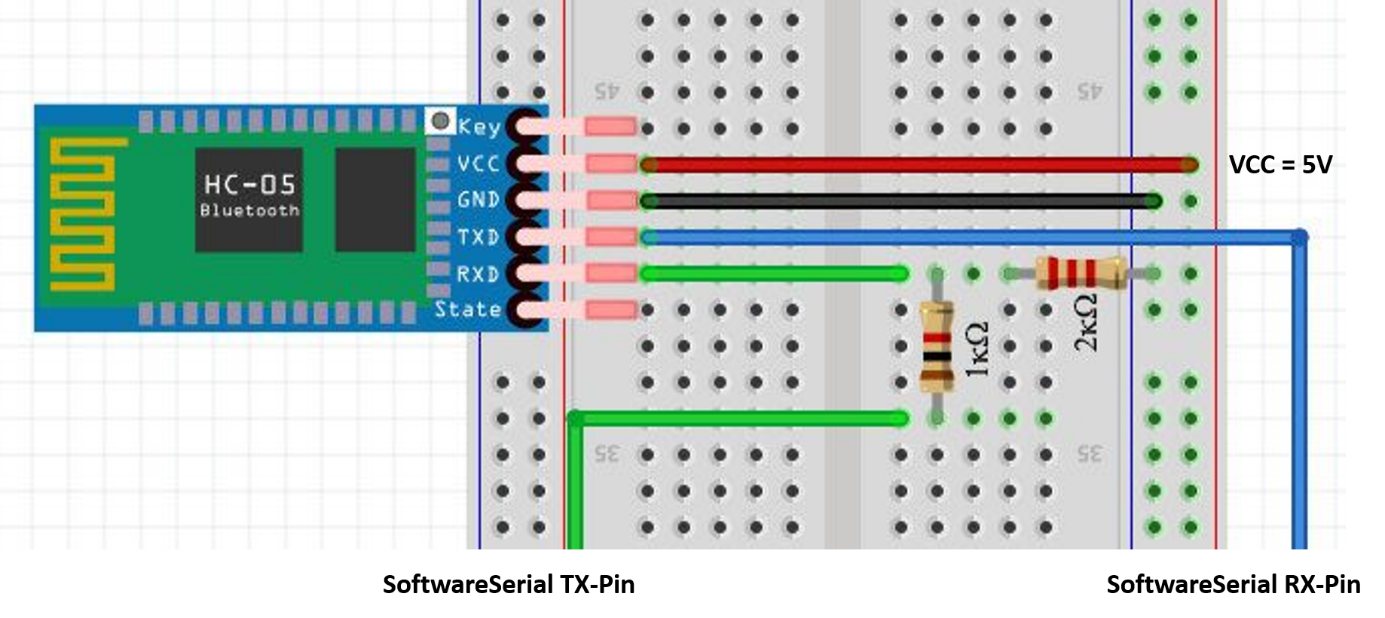
Of the six pins on the HC-05 module, only four are needed: VCC (5V) and GND for the module's power supply, and RXD and TXD for connection to two pins of the microcontroller where SoftwareSerial is set up. However, you can't ignore the inscription LEVEL: 3.3V in order not to damage the module. On our microcontroller with 5V logic, we need a voltage divider from 5V to 3.3V at least for the RXD pin, so resistors of 1 kOhm and 2.2 kOhm, for example.
The schematic: HC-05 module on the microcontroller
The AT commands of the HC-05 module for Arduino microcontroller
To the left of the connector marked Key there is a small button, which is important for the configuration. When this button is pressed during power-on, we enter the AT command mode (the LED flashes slowly in a 2s rhythm), where we use so-called AT commands (for Attention, Achtung) to make the settings. For this we use a modified example program, where the usual serial port is connected to the Serial Monitor of the Arduino IDE and the HC-05 via SoftwareSerial.
/*
Software serial multiple serial test
Receives from the hardware serial, sends to software serial.
Receives from software serial, sends to hardware serial.
The circuit:
* RX is digital pin 10 (connect to TX of other device)
* TX is digital pin 11 (connect to RX of other device) // voltage divider!
created back in the mists of time
modified 25 May 2012
by Tom Igoe
based on Mikal Hart's example
This example code is in the public domain.
*/
#include <SoftwareSerial.h>
SoftwareSerial BTSerial(10, 11); // RX, TX // mySerial changed to BTSerial
char c=' '; // Declaration of variable for transmission
void setup() {
// Open serial communications and wait for port to open:
Serial.begin(9600); // Baud rate changed to 9600
Serial.println("Serial started!");
// set the data rate for the SoftwareSerial port
BTSerial.begin(38400); // Baud rate for BT 38400
Serial.println("BTSerial started!");
}
void loop() { // run over and over
if (BTSerial.available()) {
c=BTSerial.read();
Serial.write(c);
}
if(Serial.available()) {
c=Serial.read();
BTSerial.write(c);
Serial.write(c); // re-transmission of input in Serial Monitor
}
}
The main AT commands are used in the following figure. The remote station, the HC-05, sends a response if necessary and acknowledges with OK.
We are mainly interested in the name and the HEX address in order to uniquely identify the module later on the smartphone. The AT commands are entered into the serial monitor of the microcontroller. In the following picture you can see the serial monitor of the Arduino IDE.
If you want, you can change the default password 1234 with"AT+PSWD=xxxx", where x stands for a digit from 0 to 9. Afterwards check with"AT+PSWD?" if the input was successful.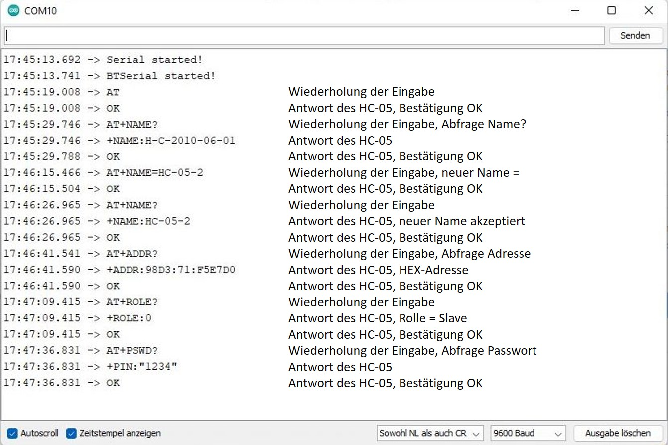
After finishing the inputs the module is disconnected from power for a short time. After switching on again without pressing a button, the HC-05 module is in standard mode. The LED flashes quickly (approx. 5 times/s).
Modifications of the RC-Car: different Motorshield
Now to the Robot Car. After we used the Motor Controller V2 last time, which only needs the two I2C connectors SDA=A4 and SCL=A5 for the control signals, this time I want to introduce the older Motor Controller V1, which blocks a lot of digital pins, but can often be bought for a bargain price.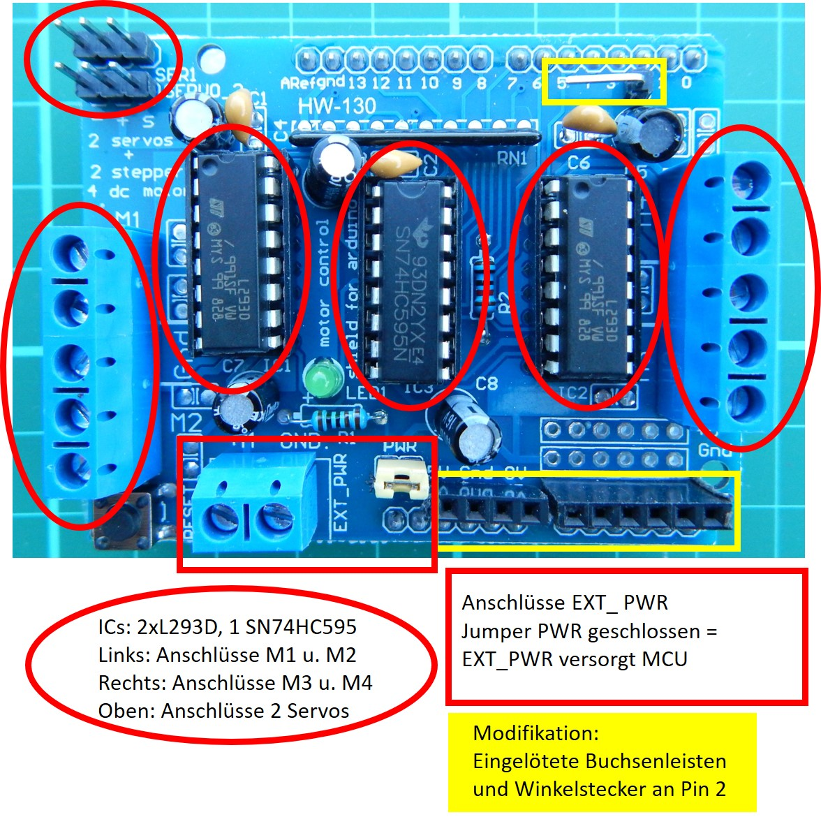
I also modified this Motorshield a bit to get access for sensors and radio receivers. On the digital pin side, there is only one pin that can be accessed using an angled connector: Pin 2. This is good for those who want to connect the IR receiver here. There are more possibilities for expansion on the other side, where you can access all analog inputs as well as the power supply with the help of female connectors (also called female headers).
Since all analog inputs can also be used as digital inputs or outputs, we have the possibility to connect our radio receivers here. This works wonderfully with the 433 MHz transceiver HC-12 (see next episode), but for the BT receiver HC-05 only with restrictions. First, we can't connect the RXD pin directly, we need the voltage divider, and second, the pins don't provide enough current to power the module on those pins.
On the following picture you can see a small adapter we made ourselves, which supplies the HC-05 with 5V and ground from the corresponding pins, connects TXD directly to RX of the SoftwareSerial interface A1 =D15 and RXD via the voltage divider to A2 = D16.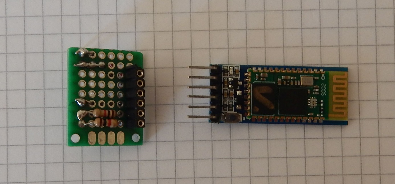
The circuit diagram: HC-05 module with L293D Motorshield on Arduino microcontroller
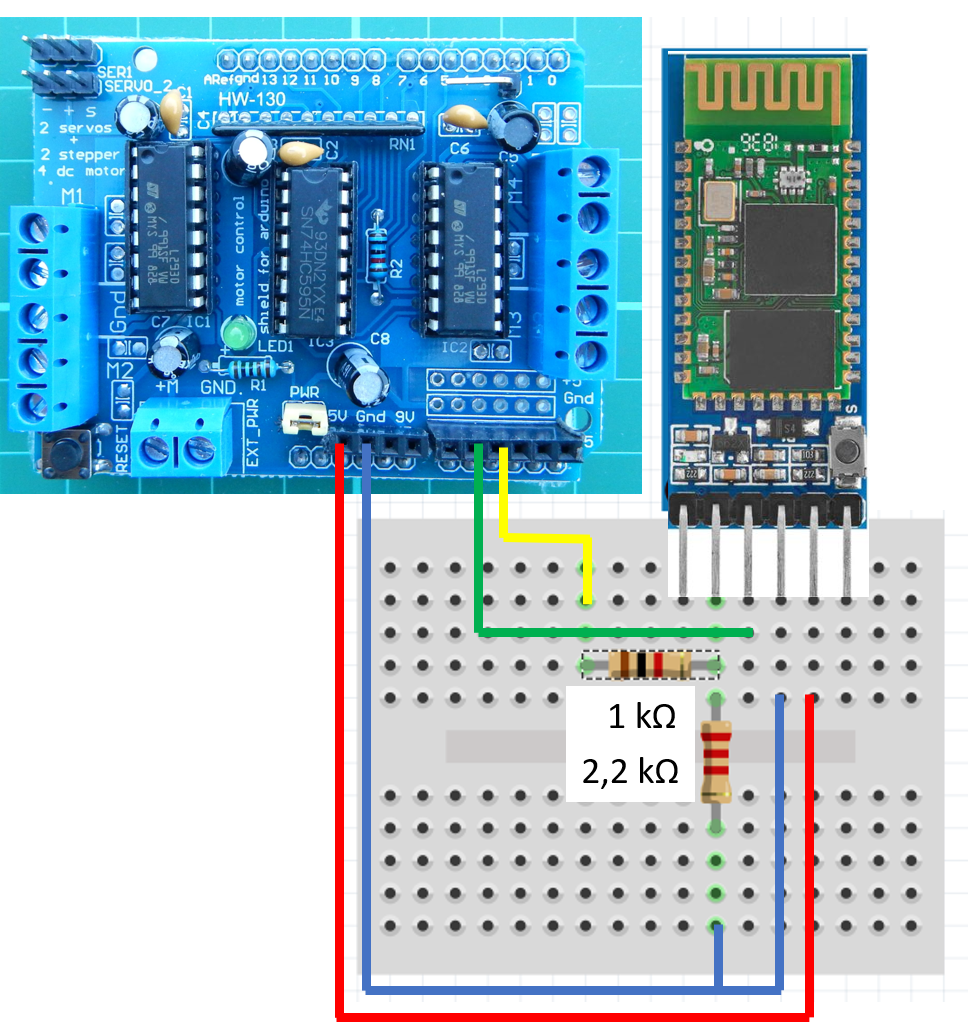
The circuit can of course also be realized on a mini breadboard with jumper cables.
Like last time, the code for the driving instructions is increased or decreased by pressing a button; this time only not with IR remote control, but with the touch function in the smartphone APP and the Bluetooth query via SoftwareSerial.
Pairing the HC-05 Bluetooth Module with an Android Application (APP)
Before the APP can connect to the Robot Car, we need to pair it with the Bluetooth module in the settings. This should be quite easy, because we have previously used the AT commands to get the name and HEX address of the HC-05.
Once the pairing has worked and a suitable BT app has been installed, it can be launched and set up. By tapping on the magnifying glass in the left picture, suitable devices are displayed. We tap on the HC-05 and get the message "connected". The app I used offers several interfaces for operation (middle image). I decided to use the game controller. On the middle picture on the top right there are two arrows forming a small circle. Please tap here if the connection is lost.
On the right picture are the buttons of a game controller. Before using them for the first time, you have to assign the numerical values to the buttons, which should be transmitted when you tap them.
For the cursor buttons I have given the numerical values 1 to 4 in clockwise direction. I assigned the numerical value 5 to the other buttons. These values are passed in the sketch to the variable blueToothVal and lead in the if-pointers of the function loop() to determine the code for the drive level.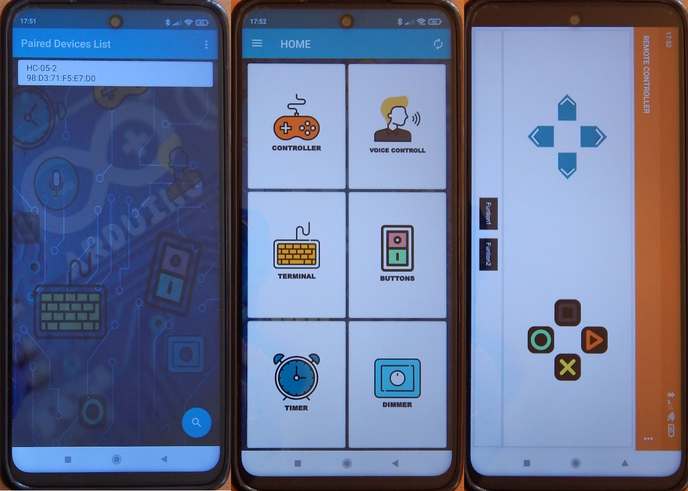
The changes from infrared to Bluetooth and motor controller V2 to V1 cause some modifications in the main part of the sketch. On the other hand, almost nothing changes in the motor() function. Only in the notation, due to the different program libraries (libraries), the functions motor1->setSpeed() now becomes motor1.setSpeed().
The program code: Build RC Car for Arduino
* Sample Code for Robot Car with Motor Shield V1 and BT receiver  HC-05, as of 20220515
* based on Adafruit Motor shield V2 library, copyright Adafruit Industries LLC
* this code is public domain, enjoy!
* modified for Funduino
* Pins
* BT VCC to Arduino 5Vout.
* BT GND to GND
* Arduino A1=15 (SS RX) - BT TX no need voltage divider
* Arduino A2=16 (SS TX) - BT RX through a voltage divider(5vto 3.3v)
*/
#include <AFMotor.h>
AF_DCMotor motor1(2);
AF_DCMotor motor2(3);
#include <SoftwareSerial.h>
// initialize HC-05
SoftwareSerial BTSerial(15, 16); // RX, TX cross to TX, RX(voltage divider)
char blueToothVal;
int x = 0;
int y = 0;
int left = 0;
int right = 0;
int code = 5555;
int speedL = 0;
float factor = 1.8; // Correction for speedLevel 255/100 * 6V/VBatt
void setup() {
Serial.begin(9600); // set up Serial Monitor at 9600 bps
Serial.println("Motor test!");
BTSerial.begin(9600); // set up transmission speed for HC-12
Serial.println("SoftwareSerial initialized!");
} // end setup
void loop() {
if(BTSerial.available()) //if data is received ...
Serial.print("available");
{
blueToothVal=BTSerial.read();//..if they should be read out
Serial.println(blueToothVal);
}
if (blueToothVal=='1') //if the Bluetooth module receives a "1".
{
if (code<9000) code = code + 1000;
Serial.print("code = ");
Serial.println(code);
}
else if (blueToothVal=='2') //if the Bluetooth module receives a "2".
{
if ((code-1000*int(code/1000))<900) code = code + 100;
Serial.print("code = ");
Serial.println(code);
}
else if (blueToothVal=='3') //if the Bluetooth module receives a "3."
{
if (code>2000) code = code - 1000;
Serial.print("code = ");
Serial.println(code);
}
else if (blueToothVal=='4') //if the Bluetooth module receives a "4".
{
if (code-1000*int(code/1000) > 200) code = code - 100;
Serial.print("code = ");
Serial.println(code);
}
else if (blueToothVal=='5') //if the Bluetooth module receives "5"...
{
code = 5555;
Serial.print("code = ");
Serial.println(code);
}
delay(200); //little delay for better serial communication and to avoid bouncing
motor();
} // end loop
void motor(){
int speedLevel[9]={-100,-80,-60,-40,0,40,60,80,100};
y = int(code / 1000);
x = int((code - 1000*y) / 100);
speedL = speedLevel[y-1];
Serial.print("code = ");
Serial.print(code);
Serial.print(" y = ");
Serial.print(y);
Serial.print(" x =");
Serial.print(x);
Serial.print(" speedL =");
Serial.println(speedL);
//Correction of speed steps for curve travel
if (x==1){
right = speedL+20;
left =  speedL-20;
}
else if (x==2){
right = speedL+15;
left =  speedL-15;
}
else if (x==3) {
right = speedL+10;
left =  speedL-10;
}
else if (x==4) {
right = speedL+5;
left =  speedL-5;
}
else if (x==6) {
right = speedL -5;
left = speedL+5;
}
else if (x==7) {
right =  speedL-10;
left = speedL+10;
}
else if (x==8) {
right =  speedL-15;
left = speedL+15;
}
else if (x==9) {
right =  speedL-20;
left = speedL+20;
}
else {
right = speedL;
left = speedL;
}
//Input the speed levels for "left" and "right
Serial.print("left = ");
Serial.print(left);
Serial.print(" right = ");
Serial.println(right);
if (left < 40 & left > -40) {
motor1.run(RELEASE);
}
if (right < 40 & right > -40) {
motor2.run(RELEASE);
}
if (left>=40) {
if (left>100) left=100;
motor1.run(FORWARD);
motor1.setSpeed(left * factor);
}
if (right>=40) {
if (right>100) right=100;
motor2.run(FORWARD);
motor2.setSpeed(right * factor);
}
if (left<= -40) {
if (left<-100)  left=-100;
motor1.run(BACKWARD);
left = -left;
motor1.setSpeed(left * factor);
}
if (right<= -40) {
if (right<-100)  right=-100;
motor2.run(BACKWARD);
right = -right;
motor2.setSpeed(right * factor);
}
} // end motor
So much for the second cheapest solution for a Robot Car with remote control (assuming you have an Android smartphone). Next time I will show how easy it is to integrate a 433 MHz transceiver HC-12. With this, even several hundred meters of range can be achieved. However, the costs increase, because now two transceivers and another micro controller are needed. See you then.


 with 830 contacts")