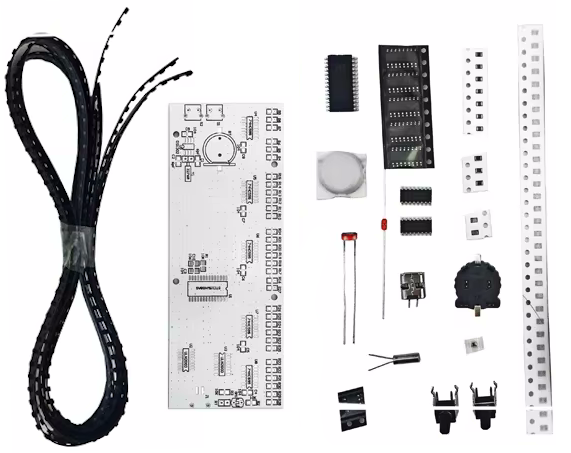
Soldering exercise SMD LED dot matrix - clock and temperature / various colors
- Item no: F23107785
- Weight: 0,04 kg
- Packing dimensions: 14 cm x 10 cm x 2 cm (L x W x H)
LED dot clock with large digits and accurate time.
This DIY LED clock consists of a white circuit board and is available with blue, red and green LEDs. The optional housing is made of transparent acrylic, which is highly transparent and durable. The included thermistor keeps you informed of changes in room temperature. Time and temperature can be displayed on the same screen, with power-off memory function.
Features:
- large digits
- corresponds to standard time
- Room temperature information
Specifications:
- Item type: Clock kit
- Model: TJ-56-240
- LED color: optional blue, green, red
- Working voltage: 3V (CR1220 battery), 5V (micro USB)
- Board color: White
- Material: Printed circuit board + electronic components + acrylic
- Dimensions (assembled): 155 x 59 x 24 mm / 6.1 x 2.3 x 0.9 inches
Scope of delivery / component list:
labeling | designation | specification | quantity |
r1 - R3 | 0805 Chip resistor | 10K | 3 |
r4 R35 | 0805 Chip resistor | 470 | 32 |
rT | glass sealed thermistor | 10K NTC | 1 |
gM1 | photoresistor | 5516 | 1 |
c1, C2 | 0805 Chip capacitor | 6 pF | 2 |
c3 - C9 | 0805 Chip capacitor | 104 | 7 |
f10 | 0805 Chip capacitor | 106 | 1 |
u1 | integrated circuit | sTC15W408AS SOP-28 | 1 |
u2 U3 | integrated circuit | uLN2003 SOP-16 | 2 |
u4 - U8 | integrated circuit | 74HC595 SOP-16 | 5 |
u9 | integrated circuit | dS1302 SOP-8 | 1 |
y1 | crystal oscillator | 32768Hz | 1 |
button battery | cR1220 | 1 | |
j1 | uSB socket | micro-USB two-pin | 1 |
s1 S2 | j1 | vertical | 2 |
sMD LED | 0603 | 390 |
Error check:
If there is no error after soldering, switch on the power test. A micro USB socket is used as the voltage source. By pressing the S2 button, you can check whether there is a faulty solder joint or a defective LED. If several LEDs in a row light up particularly brightly or even those that should not actually light up, this is due to a short circuit or an incorrectly soldered LED in a row. Pressing the S2 button takes you to the column-by-column display so that you can check individual LEDs.
Time setting:
The display time when switching on for the first time cannot be determined and must therefore be adjusted. Press the S1 button once, the hour bit of the clock starts to flash, then press the S2 button to increase the number of hours. When it reaches 23, press the S2 button again to return to 0. After setting the hour, press the S1 button again, the minute bit will start flashing and press the S2 button to increase the minutes. When 59 is reached, press the S2 button again to return to 0. After the minute bit is set, press the S1 button again to save the set time and the second bit will return to 0. Then start counting from the set time.
Notes:
- The photosensitive resistor is used to detect the ambient light intensity, and the clock can adjust the display brightness according to the ambient light. The stronger the ambient light, the brighter the LED and vice versa.
- The thermistor is used to detect the ambient temperature. When installing the thermistor. The pins should be kept longer and should not be close to the circuit board to avoid being affected by the temperature of the circuit board.


