

An LED is said to become pulsatingly brighter and darker. (Also called "fade", after the English verb to fade = to fade away, to decrease). We would like to implement this with the so-called pulse width modulation. More information about pulse width modulation on the Raspberry Pi can be found a bit further down.
In the first step, let's take a look at the schematic.
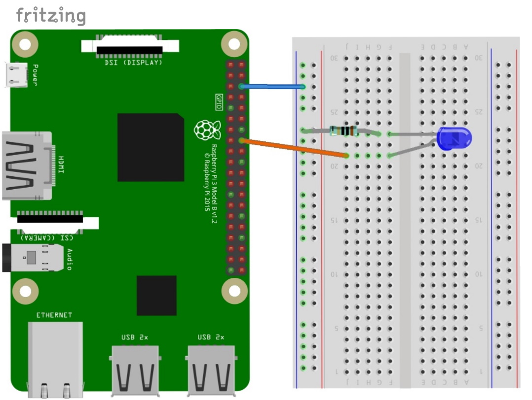
The schematic: Pulsating LED on the Raspberry Pi (PWM)
To vary the brightness of a LED, it is not enough to vary the voltage. Due to the design (diode!) a certain minimum voltage is needed; this so-called forward voltage is between approx. 1.6 and approx. 3 V, depending on the color of the LED. Above this forward voltage the LED becomes conductive, the current is limited by a series resistor. So: Unlike incandescent lamps, the brightness is not regulated by the voltage level. By the way, the GPIO pins deliver only exactly 3.3V anyway.
The remedy here is pulse width modulation (PWM). Here, the DC voltage is switched on and off with high frequency. The total transmitted energy is determined by the ratio of the duty cycle to the total duration of a cycle. This duty cycle can be between 0 and 100%.
On the Raspberry Pi you can use the software PWM on all GPIO pins. But there are also two special hardware PWM pins. Let's go!
The first program code: Pulsating LED on Raspberry Pi with pulse width modulation
# We start with importing the program modules
import RPi.GPIO as GPIO # Attention: Note the notation: small i
import time
GPIO.setmode(GPIO.BCM) # We set the mode to BCM
LED=23 # The word "LED" now stands for the number "23".
GPIO.setup(LED,GPIO.OUT) # " LED" (pin 23) is an output.
Dimmer = GPIO.PWM(LED,100) # We set the LED as PWM with a frequency of 100
Dimmer.start(0) # Dimmer is started
# Here starts the loop
try:
while True: #while loop so that the program runs continuously
for dc in range(0,101,5):         # loop of the duty cycle in steps of 5.
Dimmer.ChangeDutyCycle(dc) # change the duty cycle of the dimmer.
time.sleep(0.1) # Wait 0.1 second.
for dc in range(100,-1,-5):     # Loop the duty cycle insteps of -5.
Dimmer.ChangeDutyCycle(dc) # Change the duty cycle of the dimmer.
time.sleep(0.1) # Wait 0.1 second.
except KeyboardInterrupt: # With CTRL+C we interrupt the program
print ("Finished") # Write "Finished" in the shell window
Dimmer.stop() # Stop the dimmer.
GPIO.cleanup() # End the program.
In this example we will learn another form of loop:
the for loop. This command line also ends with a colon followed by indentation of the lines to be repeated.
The variable dc (for duty cycle) is incremented in the range 0 to exclusively 101 in increments of five:
for dc in range(0,101,5):
The second for loop counts down from 100 to -1 by -5:
for dc in range(100,-1,-5):
The second program code: Pulsing LED on Raspberry Pi with pulse width modulation using gpiozero command
# We start with importing the program modules
from gpiozero import PWMLED
import time
pwmled = PWMLED(23) # optional parameter frequency=xxx (default 100)
# here starts the loop
try:
while True: # while loop so that the programruns continuously
for dc in range(0,101,5):   #increment the tasgrad in steps of 5.
pwmled.value = (dc/100) # change the duty cycle (between 0 and 1) of the dimmer.
time.sleep(0.1) # Wait 0.1 second.
for dc in range(100,-1,-5): # Count down the duty cycle in  steps of -5.
pwmled.value = (dc/100) #Change the duty cycle (between 0 and 1) of the dimmer.
time.sleep(0.1) # Wait 0.1 second.
except KeyboardInterrupt: # With CTRL+C we interrupt the program
print ("Finished") # Write "Finished" in the shell window
# pwmled.value = 0 # 1. method toclear the LED at program end
pwmled.close() # 2nd methodto clear theLED at program end
Overall, the program code is leaner with gpiozero.
Please note: The duty cycle is between 0 and 100%. While the duty cycle argument for RPi.GPIO is the % value, gpiozero expects the value as floating point number between 0.0 and 1. 0, so instead of 50 [%] 0.5.


 with 830 contacts")
")
")
