

Origin of PWM speed controllers
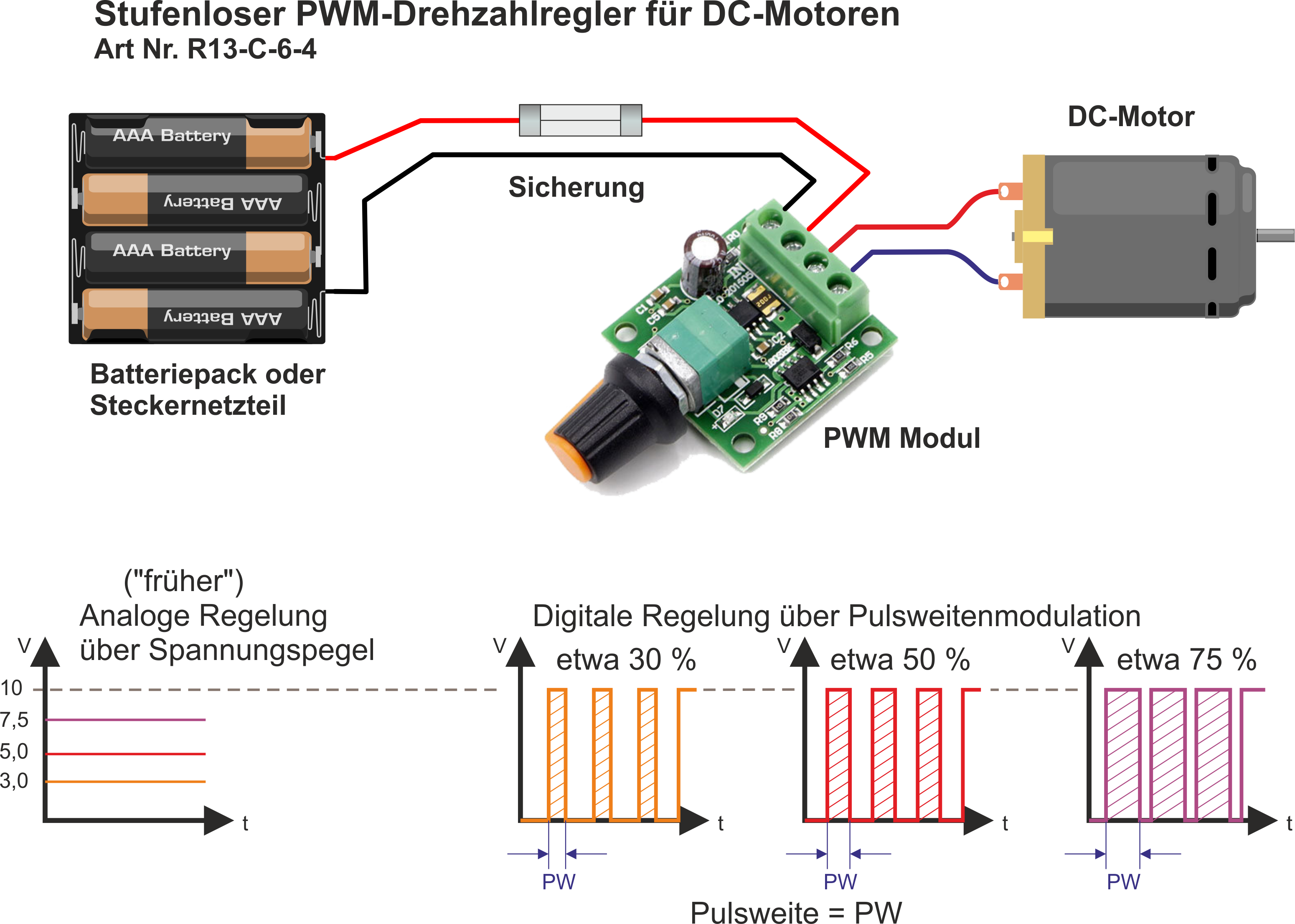
Before the development of power electronics, speed control of (brushed) DC motors was solved with linear regulators or series resistors. Figuratively speaking, one reduced the voltage (and thereby also the current) to change the speed.
However, this has some disadvantages, which become apparent especially in battery operation . Voltage and current are converted into (unused) heat energy ("burned") at the control unit (or the resistor).
The total consumption remains very high, while the usable power becomes less. Since the torque depends on the current flow, this also collapses.
How PWM speed controllers work
With (further) development of power electronics, people have approached the problem with a different idea. By (very) quickly switching the supply voltage on and off, one "pulses" the voltage (and thus the current). No power is dropped at the (electronic) switch during the "OFF" time. As a result, (almost) no more losses occur at the controller.
During the "ON" time, the FULL voltage is applied to the motor. As a result, the current - and thus the torque - is correspondingly high. Unfortunately, a motor with its coils and the iron core is not an ideal ohmic consumer, which is why this statement is not completely correct from a physical point of view.
However, the combination of coil inductance and motor inertia helps smooth the speed, so the motor behaves as if it were operated with continuous DC voltage.
This brings us to the disadvantages of pulse width modulation. Modulation with a square wave voltage leads to the emission of multiple radio frequencies. This results in EMC interference, which can lead to treacherous errors, especially with controllers.
In the low PWM frequency range (1-2kHz) there are unpleasant whistling noises at the motor. One could now simply increase the switching frequency further. But then the current does not have enough time to reach its maximum state in the coil/winding. It then oscillates between two non-stable state values, which leads to a current ripple.
Excessive current ripple increases heating in the winding package, which decreases motor performance and affects motor life .
... quite a lot of physics for a small component.
Now the good news: For motors in the power class, these disadvantages are quite acceptable.
Let's be happy about the previously described advantages.

