

There are only a few modules on the market that have generated as much hype in recent months as the MPU-6050 module. The two-in-one board combines two popular sensor features: The module can be used as a gyroscope as well as an accelerometer at the same time.
How so? The sensor includes a 3-axis gyroscope and a 3-axis accelerometer on one and the same chip. This allows to retrieve all (!) sensor values simultaneously. Thus, the hobbyist is always well informed about the current sensor position. This feature is particularly interesting for model building, especially for balancing chassis or drones.
can also access external magnetometers or other sensors via an additional master I2C bus, so that these sensor data can also be fully recorded.
A quick overview of the sensor data of the MPU-6050 (GY-521):
- Chipset: MPU-6050 (also known as GY-521)
- Power supply: 3.3 - 5V DC
- Line of freedom: 6*
- Interface: I2C
- Pin spacing: 2.54 mm
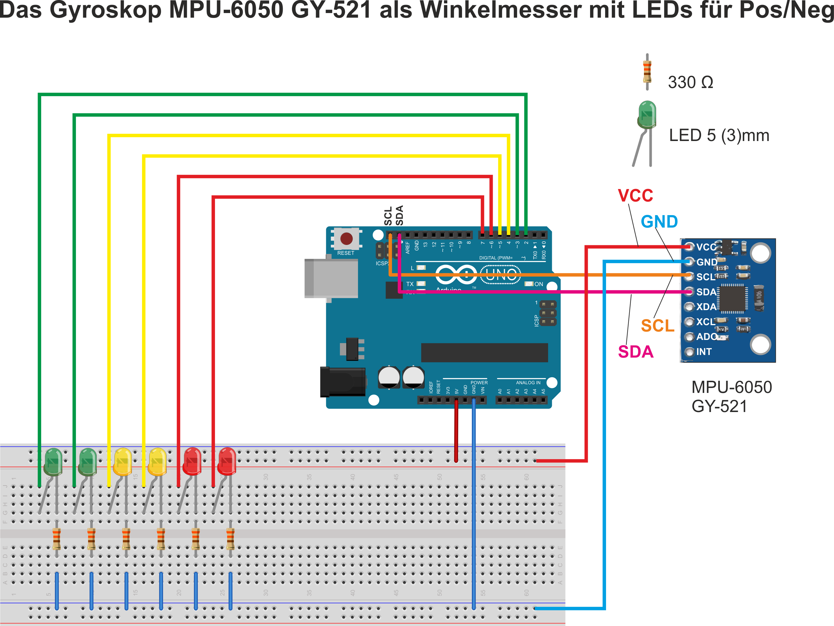
Now we come to the exciting part: the practice. To give you a nice overview of the useful functions of the MPU-6050 module, we have developed an example circuit diagram for you. The MPU-6050 module is read out by a Funduino UNO R3 and the collected data is evaluated.
We are primarily interested in the sensor data of the gyroscope. We want to read out the values of the X-, Y- and Z-axis and determine if a change of the sensor position has taken place. The change of the position should be displayed to us with colored LEDs.
So far, so good: but how do we implement this?
The program code of the MPU-6050 module
Now we get down to the nitty-gritty: well, half of it. First we have to download the appropriate library for the MPU6050 module and integrate it into our Arduino IDE. The library is called "<MPU6050_tockn.h>" and can be found and installed directly from the library management of the Arduino IDE.
After this first step we start with the actual code. First, we define the LED connections for our LEDs, which will serve us as indicators for the axis position. Then we define two variables for the axis position of each of the three axes.
Surely you ask yourself why we need two variables per axis. Since we want to determine whether the position of the respective axis has changed, we must first determine which value the sensor has recorded for the current position. We save this sensor value of the MPU-6050 for a short period of time in the first variable.
In the second variable, the value of the axis position is saved again a little later. We can now compare the two recorded measured values with each other. If a deviation of the position by a previously defined minimum value has been detected (in our code example +-3), we can assume that the sensor has changed the position. In this case we switch on the assigned LED.
Especially nice: the captured measurement data can be displayed well in the serial plotter of the Arduino IDE.
// This sketch compares the angles of the X/Y/Z axes with the previous values.
// If they are different by +/-3°, the sketch switches LEDs. (jew.1 for POS or for NEG)
// Attention: These are not the absolute values but RELATIVE values compared to the previous measurement
#include <MPU6050_tockn.h> // include libraries
#include <Wire.h> // <-
MPU6050 mpu6050(Wire, 0.1, 0.1); // Attenuate values. The smaller (direction "0"), the more nervous the values-
// the bigger (direction "1") the more sluggish the values
const int ledXpos =2; //***
const int ledXneg =3; // *
const int ledYpos =4; // * define the LED connections
const int ledYneg =5; //*
const int ledZpos =6; //*
const int ledZneg =7; //***
int xNowPos; // variable CURRENT X-Pos
int yNowPos; // Variable CURRENT Y-Pos
int zNowPos; // Variable CURRENT  Z-Pos
int xPrePos; // Variable PREVIOUS X-Pos
int yPrePos; // Variable PREVIOUS Y-Pos
int zPrePos; // Variable PREVIOUS Z-Pos
int difference = 3;
void  setup() { // Start setup function
Serial.begin(115200); // Open serial transmission (115200Baud) !!! Setup at the monitor as well !!!
pinMode(ledXpos, OUTPUT); //***
pinMode(ledXneg, OUTPUT); // *
pinMode(ledYpos, OUTPUT); // * Set that LED connectors are outputs
pinMode(ledYneg, OUTPUT); //*
pinMode(ledZpos, OUTPUT); //*
pinMode(ledZneg, OUTPUT); //***
Wire.begin(); // Start I2C protocol
mpu6050.begin(); // Start gyro
mpu6050.calcGyroOffsets(); // Gyro calculates its offsets !!! Meanwhile leave it quiet !!!
// Use mpu6050.calcGyroOffsets(true) to track it in the serial monitor.
delay(1000); // That's what we're waiting for...
}
void loop() { // Start of the loop loop
mpu6050.update(); // Create new data set in the gyro
xNowPos=(mpu6050.getGyroAngleX()); // Request new record from gyro, write to X variable
yNowPos=(mpu6050.getGyroAngleY()); // Request new data set from gyro, write to Y variable
zNowPos=(mpu6050.getGyroAngleZ()); // Request new record from gyro, write to Z variable
if (xNowPos < xPrePos-(difference)) // Compare old dataset with new one. Difference < -3 ?
{digitalWrite(ledXpos, LOW); digitalWrite(ledXneg, HIGH);} // Then switch LEDs accordingly
else if (xNowPos > xVorPos+(difference)) // Compare old data set with new one. Difference < +3 ?
{digitalWrite(ledXpos, HIGH); digitalWrite(ledXneg, LOW);} // Then switch LEDs accordingly
else // Or just turn off all X LEDs...
{digitalWrite(ledXpos, LOW); digitalWrite(ledXneg, LOW);} // Then switch LEDsaccordingly
if (yNowPos < yPrePos-(difference)) // Compare old data set with newone.  Difference < -3 ?
{digitalWrite(ledYpos, LOW); digitalWrite(ledYneg, HIGH);} // Then switch LEDs accordingly
else if (yNowPos > yVorPos+(difference)) // Compare old data set with new one. Difference < +3 ?
{digitalWrite(ledYpos, HIGH); digitalWrite(ledYneg, LOW);} // Then switch LEDs accordingly
else // Or just turn off all Y LEDs...
{digitalWrite(ledYpos, LOW); digitalWrite(ledYneg, LOW);} // Then switch LEDsaccordingly
if (zNowPos < zPrePos-(difference)) // Compare old data set with newone.  Difference < -3 ?
{digitalWrite(ledZpos, LOW); digitalWrite(ledZneg, HIGH);} // Then switch LEDs accordingly
else if (zNowPos > zPrePos+(difference)) // Compare old data set with new one. Difference < +3 ?
{digitalWrite(ledZpos, HIGH); digitalWrite(ledZneg, LOW);} // Then switch LEDs accordingly
else // Or just turn off all Z LEDs...
{digitalWrite(ledZpos, LOW); digitalWrite(ledZneg, LOW);} // Then switch LEDsaccordingly
xVorPos=xJetztPos; // Update the (so far) old data set
yVorPos=yJetztPos; // Update the (so far) old data set
zVorPos=zJetztPos; // Update the (previously) old record
// Then, in the next run, it can be compared against "before" again
Serial.print(xNowPos); // >> serial plotter<< fair notation [output X]
Serial.print(" ");Serial.print(yNowPos); // (" ") = (\t) = New color [output Y]
Serial.print(" ");Serial.println(zNowPos); // (" ") = (\t) = New color[output  Z]
delay(15); // (minimal delay calms down the serial output)
} // end of loop
// Feel free to experiment a bit with the damping in the third program line
//-> MPU6050 mpu6050(Wire, 0.3, 0.3);
// or with the delay() at the end. Afterwards observe the values in the >>serial PLOTTER <<


")
